EXOSAT ABSOLUTE SOURCE LOCATIONA Progress Report1. IntroductionEXOSAT, ESA's first scientific three-axis stabilised satellite, is maintained in stable pointing with an accuracy of approximately ± 2-3 arc seconds using gyros for attitude measurement and control of a propane gas thruster system. The overall attitude measurement accuracy is about 5-6 arc seconds. A comparison of the determined EXOSAT position and the accurately known optical/radio position of a number of X-ray sources has shown systematic differences of 4 to 15 arc seconds with a mean of approximately 10". This note describes work carried out to investigate and improve the accuracy of EXOSAT source position determination.
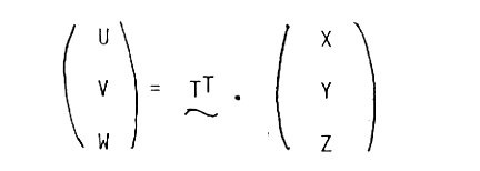
2. Coordinate TransformationsDetails of coordinate transformations, use of -the attitude information and the telescope misalignment data have been given in the FOT Handbook (Sect.7.1). For completeness, the mathematics involved is presented here.Generally, the transformation from the coordinate system (U,V,W) to a new coordinate system (X, Y, Z) involving rotation and no transition can be written as follows:
where Xu, Xv, Xw are the three components of the X unit vector with respect to U, V and W (so called direction cosines) etc. If the coordinate frames are orthogonal then the transformation matrix T is orthogonal and the inverse of T is equal to the transpose.
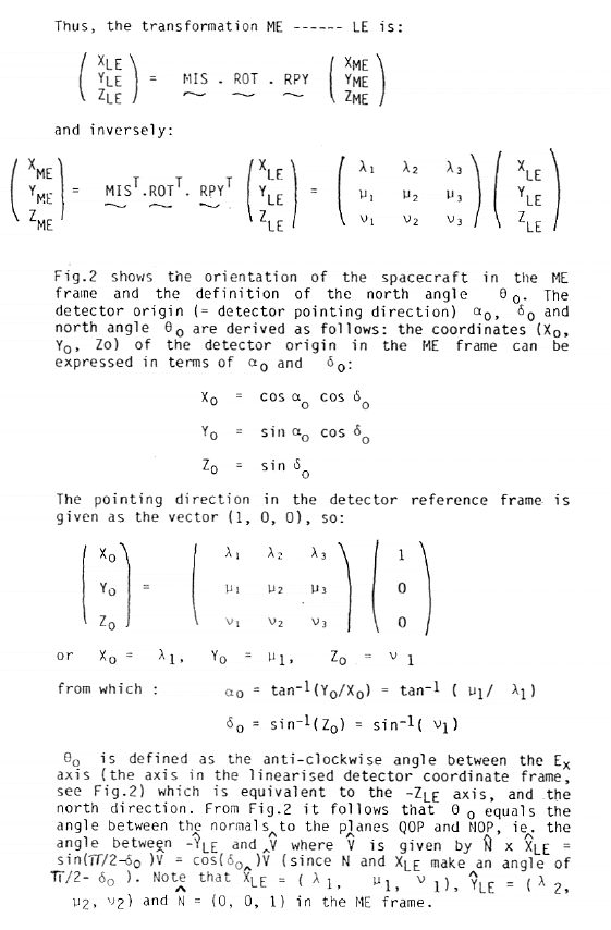
Three coordinate systems are defined as follows: 1) The star tracker reference frame (spacecraft axes): (XST, YST, ZST) 2) The LE detector reference frame (after linearisation): (XLE, YLE, ZLE). 3) The Celestial Mean Equatorial (ME) 1950 reference frame: (XME, YME, ZME) Two transformations are required to establish the relation between the detector reference frame and the Mean Equatorial frame:
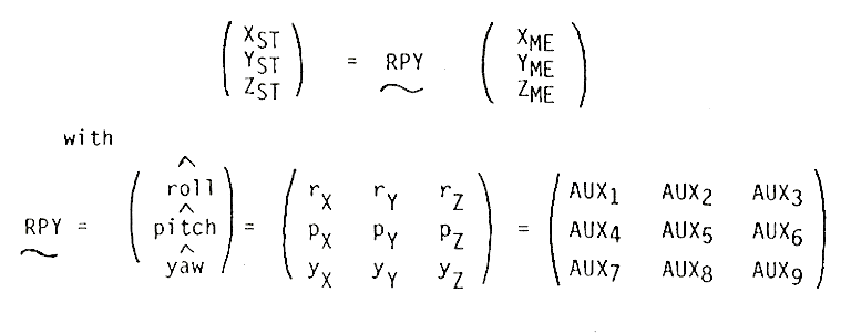
B) ST -------- LE A) The auxiliary data on the FOT contain the spacecraft attitude defined as the three components of the roll, pitch and yaw axes with respect to the ME reference frame, ie:
pitch = (pX, pY, pZ) yaw = (yX, yY, yZ)
where AUX1 .... AUX9 are the values in the Auxiliary data file on the FOT, record 3 bytes 8-124 (see FOT Handbook, Sect. 3.8 p. 11 ) . Note that these values are converted from the requested nominal pointing direction. The actual pointing direction is obtained from the star positions in the star tracker field of view ( refer to next section). RPY is the attitude matrix printed in the automatic analysis output. A 5" offset is applied to the Y-axis limit cycle to overcome an operational problem of the AOCS electronics (ref. Express No.4 p.34). This affects all observations carried out from 15.9.83 at 07.00 UT (day 253, SHF time key 116924400) and pointing positions must be corrected appropriately by an additional transformation.
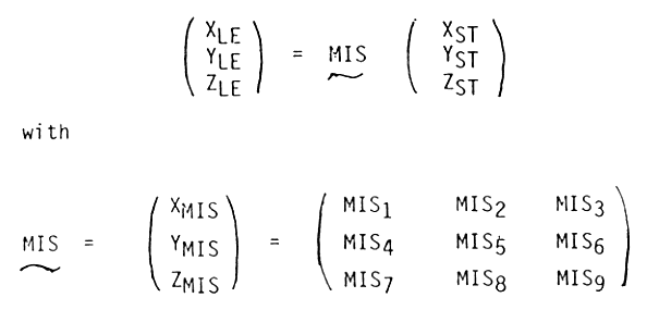
where B) The relationship between the ST and LE frames is given by the telescope misalignment data in the LE CCF (data type BD) The transformation ST ------ LE is written as:
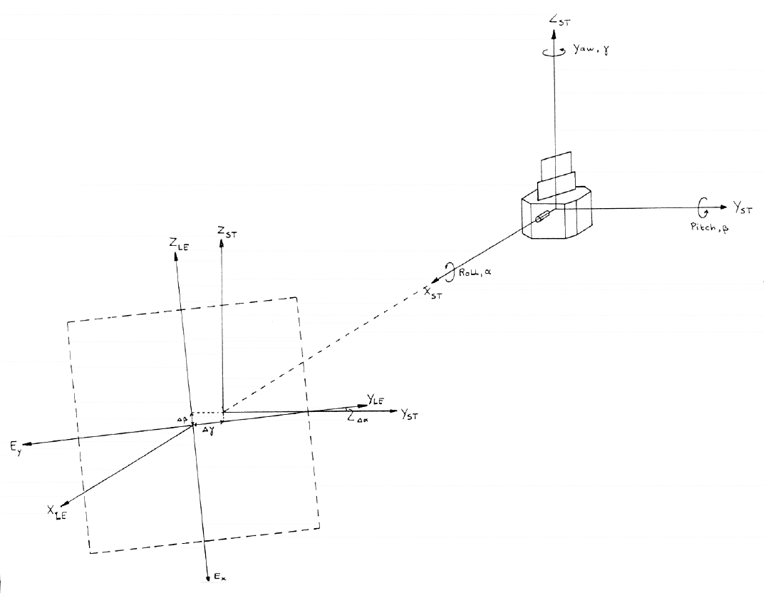
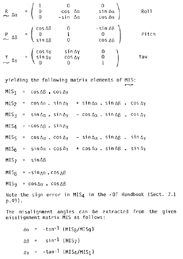
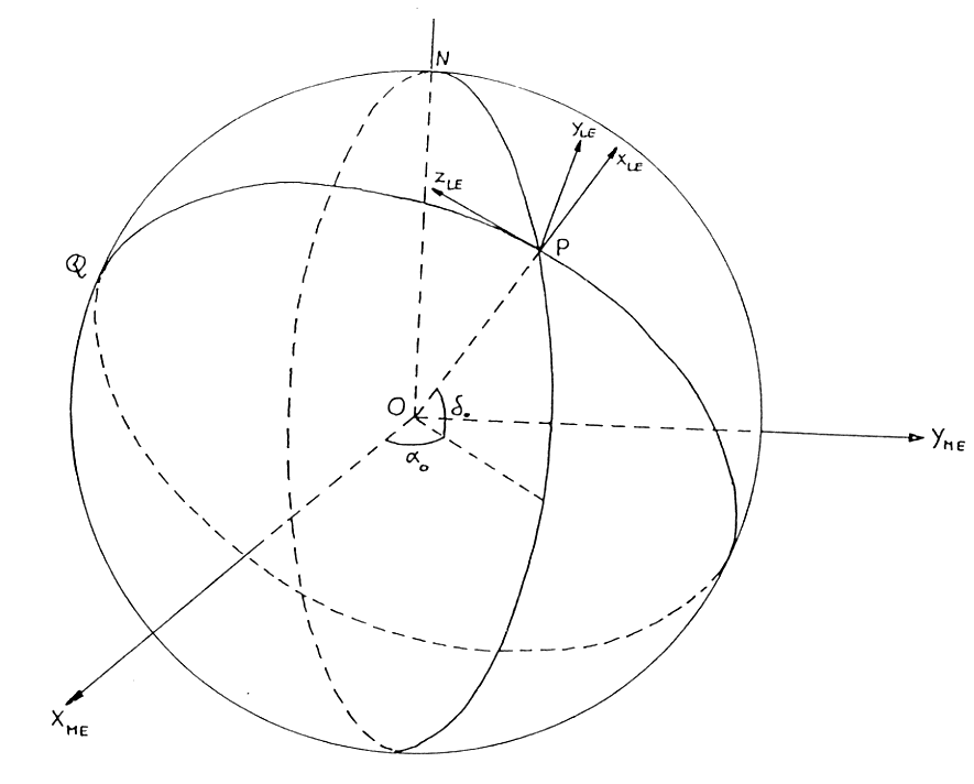
where MIS1 .... MIS9 are given in the LE CCF (data type BD) bytes 0 - 35 (CMA) multiplied by 109. The misalignment is the displacement of the LE frame with respect to the ST frame (see Fig. 1) and can be derived in terms of 3 consecutive rotational matrices about the roll, pitch and yaw axes:
where
3. ResultsAn analysis of a number of EXOSAT X-ray sources with known optical or radio counterparts and no detectable proper motion has been carried out and the results are summarised in Table 1. Source positions were taken from the compilations of Burbridge et al. (1977), Lang (1980), Weller et al. (1980) and Clements (1981). The fourth column of Table 1 gives the day of observation and the next three columns the resulting number of counts (cts) and the position xb, yb in the L1 CMA, determined as the baricentre of the distribution of the source counts corrected for background obtained from regions outside the source location.
EXOSAT RA and Dec. positions are derived using the formula given in the FOT
Handbook (Sect. 7.1 p.46). The 5" offset of the Y-axis limit cycle and
refinements to the accuracy of the calculation were included. Columns
Secondly, a correction has been applied for the typical limit cycle of ± 2-3
arcseconds maintained during an observation. Image 'deblurring' was carried
out by the simple method of calculating the mean offset (pixels) in pitch
(
 Yd = Yb - 
 and and
 , of the order of 10", were calculated.
In general, , of the order of 10", were calculated.
In general,  and and
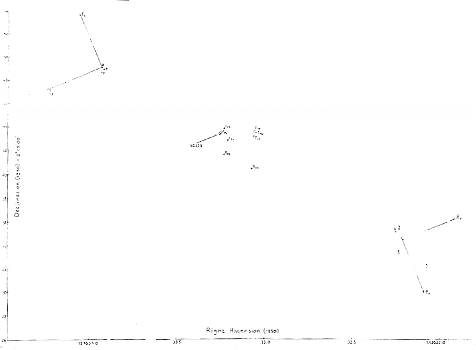
 are less than ~2". are less than ~2".Two X-ray sources (3C273 and 1156+295) in the sample have twice been observed about half a year apart, with opposite orientation of the spacecraft. Fig. 3 shows the computed 'deblurred' positions for 3C273 together with the orientation of the Ex, Ey plane of the L1 CMA. The source was observed using different filters yielding a number of positions which are within a region of about 4" diameter. A systematic error is clearly present, the two sets of observations each being located opposite the true source position and about 30" apart. Observations of 1156+295 show the same behaviour suggesting a telescope to star tracker misalignment error. This error has been calculated empirically by taking for each set of observations the difference in the Ex and Ey direction:
giving the following errors in the misalignment angles (see Fig.1).  = X/2= -11.83" = X/2= -11.83"  = Y/2= +10.18" = Y/2= +10.18"
If this correction is applied to the misalignment angles, new
positions and deviations
In July 1985, improved star tracker calibration reference data was
implemented at ESOC (p.2) yielding a better knowledge of the actual pointing
direction. Generally, the calculated (requested) pointing direction is within
~1" of the actual one. As a final correction to the EXOSAT positions, this
new calibration data gave slightly improved deviations
There are a few exceptions to this, some of which may be caused by the
linearisation of the detector read-out positions. The linearisation for LE1
is based on an in-flight raster scan (Cyg X-2), which is less accurate than
the ground-based calibration for the LE2 CMA. However, close to the detector
origin, where the linearisation is most accurate, In some cases, poor statistics (<~ 50 cts) may yield inaccurate positions, see eg. the third pointing of MKN 421, where Yb is about 1 pixel less than the two previous values.
4. Conclusions and Status of Analysis SoftwareFor a small sample of X-ray sources accurate positions have been determined by including in the analysis the following factors:
Further work is in progress to:
(A) Interactive Analysis system
(B) Auto analysis softwareNo modifications
E. Gronenschild
ReferencesBurbridge, G.R., Crowne, A.H., Smith, Harding, E. Ap.J.Suppl., 33, 113 (1977).Clements, E.D. M.N.R.A.S. (1981), 197, 829. Lang, K.R. Astrophysical Formulae, p.195 (1980). Weller. K.W., Johnston, K.J. M.N.R.A.S. (1980), 190, 269. Figures
Page authors: Lorella Angelini Jesse Allen HEASARC Home | Observatories | Archive | Calibration | Software | Tools | Students/Teachers/Public Last modified: Thursday, 26-Jun-2003 13:48:32 EDT |



 = +5".

 ,
,
 and
and
 are the anti-clockwise rotational angles (misalignment angles) as
seen from the respective positive axis in the direction of the origin (
 and
and  give the deviations (arcsec) of the EXOSAT position with respect to
the known optical/radio position (column 2 and 3).
 and
and
 are derived. These deviations are typically less than ~7".
 and
and
 .
.
 ,
the corresponding distance, is now typically ~6".
 and
and
 .
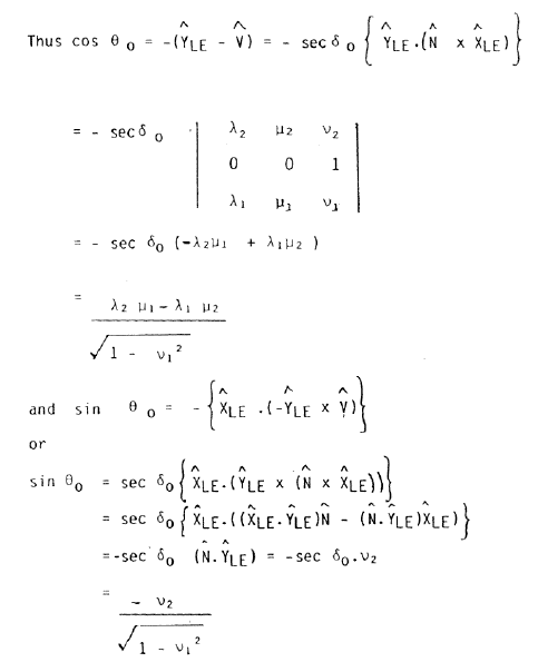
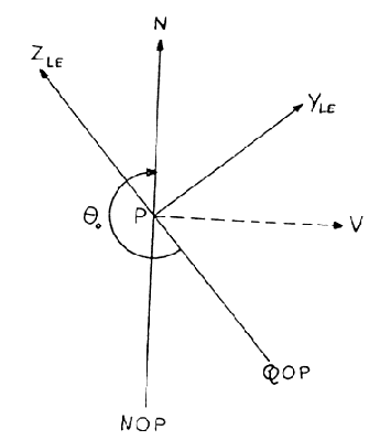
The north angle
  is defined as shown (b).