


Next: Off-Axis PSF
Up:
In-flight Point Spread
Previous:
In-flight Point Spread
|
E | % photons outside |
|
(keV) | a 10'' radius |
| 0.18 | 0.7 |
|
0.28 | 1.3 |
|
0.93 | 6.0 |
|
1.49 | 11.0 |
|
1.70 | 13.3 |
Table 5.2: Energy dependence of the mirror scattering
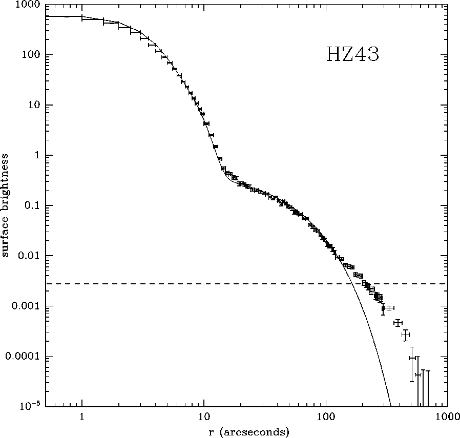
Figure 5.1: The point spread function from a long exposure of HZ 43.
The surface brightness is in units of counts per pixel.
To improve the statistics, the data were binned in increasingly
larger annuli (0.5, 1, 2, 4, 10, and 60 arc seconds).
The dashed line is the background rate in this observation
determined between 8' and 12' off-axis.
Also shown is the parametric form for the PSF.
Although the XRT PSF has a central core with a FWHM of 3''
(as determined by ground test), microroughness in the mirror
surfaces leads to a slight but measurable scattering of X-rays
and produces a small energy-dependent tail or wing in the PSF.
As determined by ground test measurements, the fraction of imaged
photons in the tail (beyond 10'') of the image of a point source
is given in
Tab. 5.2.
The HRI PSF has a central core with a FWHM of 1.7''
(as determined in the laboratory).
In the absence of the electrostatic shield, the PSF has a
near-Gaussian shape, but the electrostatic shield (introduced
to reduce the background count rate) has broadened the PSF,
creating a so-called ``halo''.
X-rays interacting in the interchannel web in front of the MCPs
produce electrons that are ``captured'' in microchannel pores
a considerable distance from the initial event site, initiating
an electron avalanche leading to a false position.
Although the region between the shield and the MCP is,
to first order, field free, fringe electrostatic fields deflect
the web electrons back into the MCP.
The magnitude of the effect is predicted to decrease with
increasing energy, whereas mirror scattering increases with energy.
The in-flight, on-axis PSF, which includes aspect solution effects,
has been determined from a 9.1 ksec exposure of HZ 43 which yielded
109,000 net counts.
Figure 5.1
shows the azimuthally averaged surface brightness profile of this
observation.
The HRI halo is obvious in
Fig. 5.1
and dominates the PSF beyond approximately 15''.
The solid curve is a parametric representation of the in-flight,
on-axis, PSF and consists of the sum of two Gaussians
and an exponential.
This functional form for the azimuthally averaged PSF, provides a
good description of the PSF out to a radius of 2', and is given by:

where the radial distance, R, is in arc seconds, and:
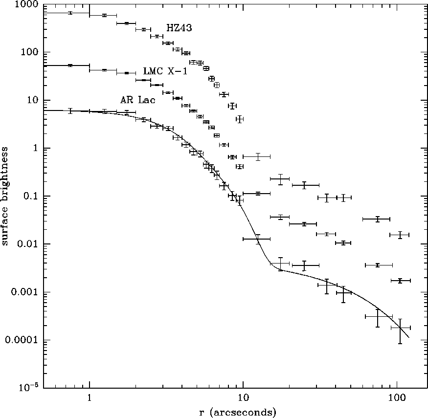
Figure 5.2: A comparison of the point spread functions of HZ 43,
LMC X-1, and AR Lac with arbitrary normalization.
To improve the statistics, the data were binned in increasingly
larger annuli (0.5, 1, 2, 5, 10, and 30 arc seconds).
Also shown is the parametric form for the PSF normalized to
the AR Lac observation.
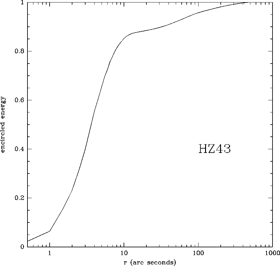
Figure 5.3: The on-axis encircled energy function from a long exposure of HZ 43.
The profile has been normalized to unity at 8'.
This figure shows that approximately 15% of the power is
scattered beyond 10'', 7% is scattered beyond 1',
and less than 1% is scattered beyond 5'.
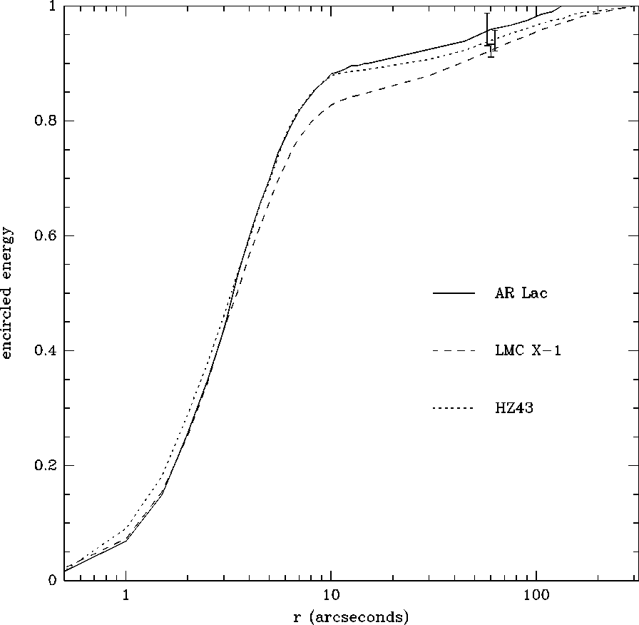
Figure 5.4: A comparison of the on-axis encircled energy functions
for observations of HZ 43, LMC X-1, and AR Lac.
Some extended emission is evident in the profile of LMC X-1.
The error bars shown in the figure were all evaluated at 1',
but were offset slightly on the graph for clarity.
Note the arbitrary normalization of the above expression for the
azimuthally-averaged surface brightness.
Figure 5.1
shows that there is an additional component in the PSF beyond 2',
but this component will be well below the background in most
observations.
We have not fit this additional component, since we do not know
at present how strongly it depends on energy.
The azimuthally averaged surface brightness for on-axis
observation of HZ 43, AR Lac and LMC X-1 is shown in
Figure 5.2.
Since these sources represent a wide range of mean X-ray energies,
this figure demonstrates that the combined PSF (HRI/XRT) is
largely energy independent within 2'.
The integrated surface brightness (encircled energy function) for
the long HZ 43 observation is shown in Figure 5.3.
The extended HRI halo is evident in this figure and shows that
approximately 15% of the total power is scattered beyond 10'',
7% beyond 1', and less than 1% beyond 5'.
Figure 5.4
shows the encircled energy function for HZ 43, Ar Lac, and LMC X-1.
This figure shows that the encircled energy function is consistent
within the statistical errors for these three sources, and is not
strongly dependent on the photon energy.
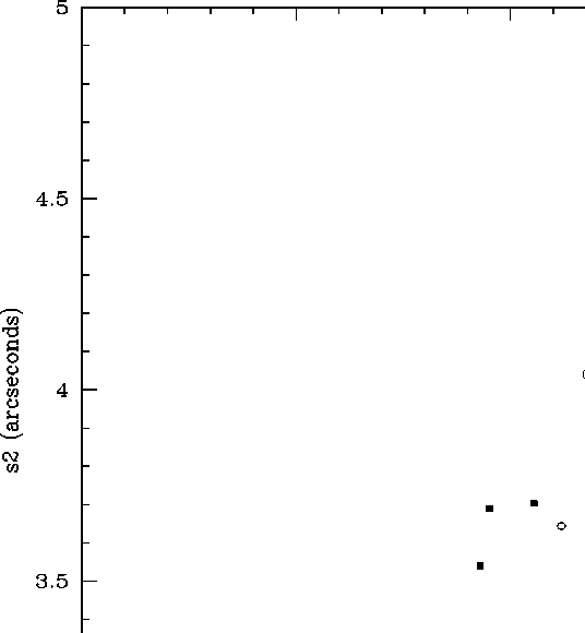
Figure 5.5: The best fit values of  and
and  to a sample of
point sources observed nearly on-axis (within 3').
The pair of values in the on-axis PSF given above is shown
as an open square. Observations of the meaty source
are indicated by open circles.
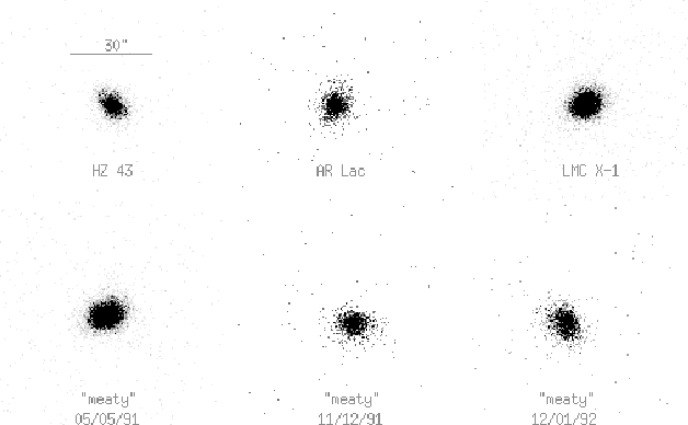
Figure 5.6: Comparison of several nearly on-axis (within a few arc minutes)
HRI images of point sources. While the core of the images are
symmetrical, the surface brightness between 5'' - 8'' can
exhibit some asymmetry. This feature is randomly oriented
(i.e., it is not in the direction of the wobble) and depends on
the date of the observation. The three images at the bottom
of the figure show the WFC ``meaty'' source observed at three
different times.
Notice that the asymmetry is present in the first and last
observation, but not in the intermediate observation.
The on-axis PSF given above is based on a single long observation
of HZ 43 with excellent photon statistics.
Such an observation is required in order to accurately parameterize
the HRI halo.
We have also looked at a number of shorter (nearly on-axis) observations
of HZ 43, AR Lac, LMC X-1, and the meaty source taken throughout the
mission in order to determine the reproducibility of the on-axis PSF.
In general, there is no difference (within the statistics) beyond 10''.
This indicates that the HRI halo is stable and approximately energy
independent.
However, due to random errors in the aspect solution,
the width of the core of the HRI images can vary.
Fitting the above functional formof the PSF to this sample
(treating the width and normalizations of the two gaussians
as free parameters) shows that the best fit value of  varies
from 1.9'' to 2.5'', and the best fit value
  of varies
from 3.5'' to 4.1''
(see Figure 5.5).
Variations in
  and
and  between observations of the same source
(eg. the meaty source) span almost the entire range of values
shown in
Figure 5.5.
Residual errors in the aspect solution also occasionally
produce asymmetrical features in the PSF.
Figure 5.6
displays images of the so-called ``meaty source''
(a white dwarf star newly discovered with the WFC)
illustrating the inner core's appearance when the aspect
solution is correct and when there are errors leading to an
ellipsoidal image.
The major axis of the ellipsoidal images are not aligned with
the wobble direction.
The asymmetry is the strongest between 5'' and 10'' from
the centroid of the image and can have amplitudes up to 30%.
When possible, the user should use the image of a known point
source within 5' of their target as a template for the HRI PSF.
The actual two-dimensional PSF has a 16-fold-symmetrical pattern
(``radial spokes'') caused by the shadowing of mirror-scattered
X-rays by the mirror-support structure, as well as an ellipsoidal
component due to an imperfect aspect solution.
The radial spokes should only appear in images with large numbers
of detected photons in observations which are not ``wobbled''.
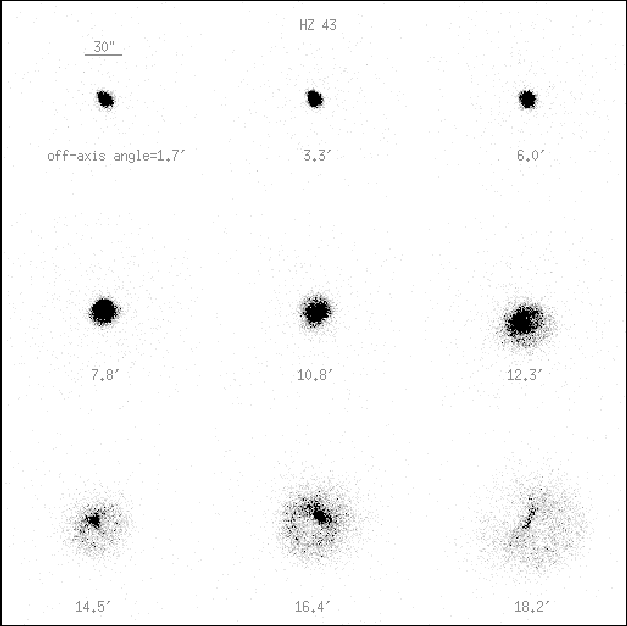
Figure 5.7: HRI images of HZ 43 at nine different angles off-axis.
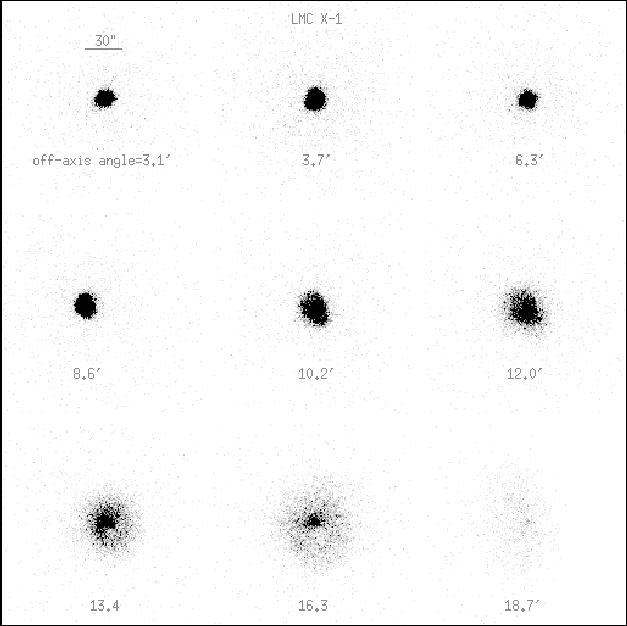
Figure 5.8: HRI images of LMC X-1 at nine different angles off-axis.


Next: Off-Axis PSF
Up:
In-flight Point Spread
Previous:
In-flight Point Spread
If you have problems/suggestions please send mail to
rosat_svc@mpe-garching.mpg.de


