The instrument teams are responsible for the calibration of instruments, which they will release in the form of documents, software, and calibration files. The latter are released to the public through the calibration database (CALDB; section 7.3). Suzaku GOF is responsible for obtaining the calibration products from the instrument teams and providing them to GOs.
In cooperation with the instrument teams and the OGIP CALDB team, Suzaku GOF will provide a set of documents which describe the Suzaku calibration. These documents should be public and available on-line in text, postscript, pdf or HTML format. At minimum, the document set should cover the following subjects:
Suzaku GOF will help the hardware teams document the calibration activities. It will be necessary to document when and how the ground and in-orbit calibrations are conducted, and which parameters are determined. Configuration of the calibration experiments should be illustrated.
Origins, formats, meanings, and usages of the calibration files stored in the CALDB (section 7.3 and 7.4) should be explained.
The algorithms for constructing instrumental responses and perform instrument specific corrections using calibration files and software should be explained. For example, it should be explained how RMFs and ARFs are created from spectral files, and how exposure maps are made from event files and attitude files.
Important satellite and instrument parameters determined through calibration should be summarized. These parameters include, for example, positions of the optical axis for each sensor.
The instrument teams are responsible for documenting the limits of current calibration, such as the systematic uncertainties in the latest spectral responses.
Calibration software are developed by the instrumental teams, and will be incorporated into the function libraries (section 4), simulation software (section 5.2), and response generators (section 6.5.3). Suzaku GOF will make the calibration softwares conform to the Suzaku software conventions (chapter 3).
When constructing instrumental responses or carrying out instrument specific corrections, it is important that algorithms and parameters be separated as much as possible. The calibration software should not include hardwired parameters, instead reading instrumental parameters from the calibrations files. This ensures that, when parameters are updated by a new calibration, only calibration files need be changed, and will make it possible to test different responses simply by changing parameters.
Suzaku calibration files shall be put in the HEASARC Calibration Database (CALDB)7.1, which also contains calibration files for other high energy missions. All the calibration files in CALDB should conform to the OGIP standard FITS format.
The master copy of the CALDB is located at GSFC under the anonymous ftp directory,
ftp://heasarc.gsfc.nasa.gov/caldb/. There are two sub-directories,
docs and data (for documents and data respectively), and those
for a particular mission are stored in
docs/[mission] and data/[mission], where [mission] is the mission name.
There are instrument directories
data/[mission]/[instrument] for each instrument,
and each directory contains three sub-directories,
pcf, bcf and cpf, which respectively stands for the primary calibration files,
basic calibration files and calibration product files.
Primary calibration files are raw or almost-raw calibration data, and will not be directly used to construct instrument responses. Ground calibration data will be archived and regarded as Primary calibration data. Calibration files used to perform instrument specific corrections or to construct responses are called basic calibration files. Responses themselves or calibration files used in the Stage 3 data analysis (section 6.5.4) are called calibration product files.
In the case of ASCA, we did not have primary calibration files. The GIS and SIS teldef files, which carry important instrumental parameters such as dimensions, misalignments and positional gain variations of the sensors, are examples of the basic calibration files. SIS and GIS RMFs are categorized as calibration product files and put under the cpf directory. In the case of Suzaku, we may archive ground calibration data under pcf. Most of the important calibration files listed below (section 7.4) are considered basic calibration files.
Some calibration files will be time-dependent.
If the variation is long enough (
![]() a few months)
and/or the results should be checked by an expert of the instrument,
the calibration files may be put in CALDB.
The HXD gain history and XIS CTI correction are such calibration data.
If the variation is as short as the span of a single observation,
the calibration files are created in the pipeline processing
although there are no current examples for Suzaku7.2
a few months)
and/or the results should be checked by an expert of the instrument,
the calibration files may be put in CALDB.
The HXD gain history and XIS CTI correction are such calibration data.
If the variation is as short as the span of a single observation,
the calibration files are created in the pipeline processing
although there are no current examples for Suzaku7.2
Calibration files should be given unique names to indicate their contents and dates of the release, and a file name and the physical file should have one-to-one correspondence; hence symbolic links should not be used. The calibration files must have the mandatory CALDB keywords which describe the nature of the files and are referenced by CALDB softwares. Recommended naming convention for the Suzaku calibration files is the following:
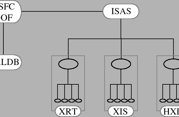
It is essential that the calibration files be under version control and releases be conducted using a well established procedure. Suzaku GOF and instrument teams have established the standard procedure for the delivery and release of calibration files. For each calibration file, there shall be a contact person in the instrument team and in GOF. To avoid confusion, those files are passed through contact persons in GOF and ISAS. After they checked the validity of the file and agreed to release, the file will be shipped to CALDB (Figure 7.1).
CALDB already has an established scheme of the version control.
Each instrument directory
(/caldb/data/[mission]/[instrument])
has the
index file named caldb.indx which contains brief descriptions for all the
calibration files included in this directory and the sub-directories. These information are taken from
the mandatory CALDB keywords in each calibration file.
Also in the caldb.indx file are quality and validity flags of all the calibration files which
are to be judged by Suzaku GOF and instrument teams.
The CALDB access software, provided by the CALDB team, can choose the
appropriate file based on the validity date and other information in
caldb.indx.
The identical CALDB tree is mirrored to ISAS regularly, although the primary copy of the CALDB is maintained at GSFC. GOs can obtain and install the entire CALDB on their machines, obtain the subset necessary for their analysis, or remotely access CALDB at GSFC or mirror sites.
Suzaku GOF and the instrument teams will determine the types of calibration files that are necessary. Important calibration files are listed below.
Alignments between the telescopes and instruments are described. In addition, parameters of the instruments and the coordinate systems, such as focal lengths and detector pixel sizes are written. There may be separate telescope definition files for different detectors.
Parameters for conversion from the digitized HK telemetry to the physical units are stored in the multimission database named Satellite Information Base (SIB) located at ISAS. Essential parts of the SIB will be extracted and put in the calibration files. These calibration files are used to interpret HK parameters in the telemetry (section 4.1.4).
The XRT effective area corresponding to a certain encircled radius is given as a function of energy for different off-axis and azimuthal angles. Separate files are made for XRT-I and XRT-S. If the four XRT-Is have different effective areas, there shall be more than one file for XRT-I.
These files are made from calibration measurements and ray-tracing simulations (section 5.2.3), and used to calculate ARFs and vignetting maps (section 6.5.3).
Although point spread functions can be created from ray-tracing simulations, a set of ready-made point spread functions for different off-axis and azimuthal angles, and possibly for different photon energies, will be provided for convenience.
Point spread functions are necessary when making ARFs (section 6.5.3) and for image analysis such as image fitting and image deconvolution.
The ray-tracing program (section 5.2.3) requires two calibration files describing the telescope parameters, one for reflectivity and the other for geometrical structure of the foils.
Variable instrumental parameters required to
calculate PI from PHA for building spectral responses
and effective area
are written as functions of time.
Gain history (pulse-peak of the calibration source),
Charge Transfer Inefficiency (CTI), quantum efficiency and
the OBF contamination will be such
examples.7.4Positions of the bad pixels and columns may also slowly vary with time.
The ![]() code database is updated when an observation uses a new CCD clock pattern.
code database is updated when an observation uses a new CCD clock pattern.
Important time invariant XIS parameters such as area of calibration masks and DAC setup are written.
Energy dependent collimator transmission is written as a function of the pointing vectors on the satellite frame. The direction which gives the maximum transmission becomes the bore-site. This file will be necessary to make HXD ARFs.
Important detector parameters required to build responses are written. These parameters should include, e.g., dimensions of the GSO crystals, silicon PIN diodes and the detector assembly. This file will be necessary to make HXD RMFs.
History of the energy gain of the PIN, GSO, and WAM detectors are written.
Process to generate GHT: There are two types of GHTs, GHT_daily and GHT_caldb.
GHT_daily is automatically generated with hxdmkgainhist every observation
(one file for each detector - PIN, GSO - per observation, not per FFF)
and stored in the Trend Archive.
GHT_caldb is generated from GHF_daily by the HXD team and stored in CALDB.
The task hxdpi calibrates the data with the latest GHF_caldb in any processing.
The update intervals are TBD (possibly, ![]() 1 month).
1 month).
The HXD background is modeled empirically (section 6.5.3). Model parameters necessary to construct HXD background will be stored in the calibration file.