The EXOSAT Ground System and In-Orbit Performance of the Spacecraft
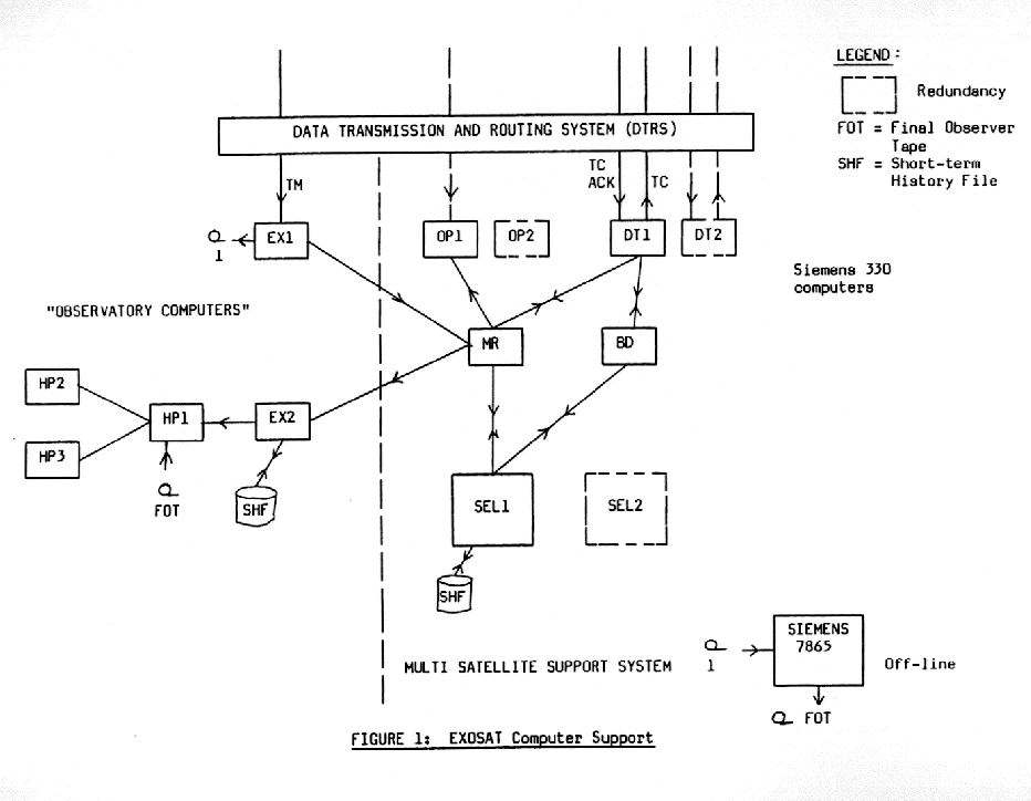
1. IntroductionThe aim of this article is to give a summary of the ESOC Ground System support for the EXOSAT spacecraft and to present some details of the in-orbit performance of the principal spacecraft subsystems. 2. EXOSAT Ground System2.1 FacilitiesThe EXOSAT facilities comprise three areas, namely the Ground Station, the Communications and the Operations Control Centre (OCC) at ESOC, Darmstadt. The dedicated EXOSAT Ground Station, located at Villafranca del Castillo near Madrid, consists of a 15-metre S-band antenna, telemetry, telecommand and ranging equipment located in the station Main Equipment Room, a Monitor and Control (M&C) Computer and a communications computer. With the exception of the antenna, all equipment is duplicated for redundancy. The station equipment is controlled on a 24-hour per day basis from a centralised M&C console by an operator in continuous voice contact with the EXOSAT Spacecraft Controller at ESOC (see 2.2). A local commanding capability together with display facilities for selected telemetry parameters is provided by the station computer. This facility is only used as a back-up in the event of failure either in the communications system or in the OCC computer system and, in any case, strictly under voice control by the EXOSAT Spacecraft Controller. Communications with the OCC for telemetry and telecommand transmission comprise three full duplex data lines, driven by high-speed modems, and routed by the Deutsches Bundespost and the Spanish PTT. Telemetry is routed in parallel on two OCC performs automatic line selection based on data quality checks. Telecommands are routed from ESOC on the third data line. A fourth line, which serves as a back-up for the telecommand line is used for all voice communication between ESOC and Villafranca (multi-project). At the OCC, there is a Dedicated Control Room (DCR) housing 5 consoles, 4 of which are at the disposal of Observers and the Observatory Team and the fifth is manned on a 24-hour per day basis by the EXOSAT Spacecraft Controller (SPACOW) All consoles have CRT's for alphanumeric display of telemetry and, in addition, the Observatory consoles have colour graphics display11s for presentation of payload data. There is a large area "wall display" at the rear of the DCR which is telemetry-driven and gives a synoptic overview of the status of the instruments and the spacecraft subsystems. EXOSAT support is provided by the computer system shown in Figure 1; the computers on the left of the dotted line are EXOSAT-dedicated while those on the right are shared with other Projects (the so-called Multi-Satellite Support System, MSSS). MSSS concurrently supports OTS, MARECS-A and GEOS; METEOSAT has a dedicated computer system. To the maximum extent possible, EXOSAT has made use of previously existing MSSS software, mainly in the areas of housekeeping telemetry, processing and display tasks and telecommand handling. Special purpose software was however developed to support, in particular:
2.2 Operations SupportOperational control of the round system is carried out within ESOC on a multi-sate lite basis. 24-hour per day support is provided for MSSS operation, network control and data routing control under the responsibility of a Shift Co-ordinator. Maintenance of the ground facilities, hardware and software, is done during normal working hours, with call-out emergency support available at all other times. EXOSAT Spacecraft Operations are undertaken by a team of engineers, technicians and Spacecraft Controllers. The SPACON position is manned on a 24-hour per day basis; he is responsible for all routine EXOSAT monitoring and control activities. Timelines for EXOSAT operations are determined from the Planned Observation File (POF) and certain other auxiliary subsystem activities such as perigee and eclipse preparation. Each POF is constructed on an orbit by orbit basis from the Observatory Team's schedules which are produced in roughly 4-8 orbit blocks from the list of approved AO observations. Payload and OBC configuration is determined for each observation by the Observatory team and is implemented by the SPACON on the request of the Duty Scientist. Preparation, execution and monitoring of attitude manoeuvres is a primary task of the SPACON. Monitoring of all telemetry data is performed automatically and continuously by the MSSS and the SPACON is alerted if any limit - or status - check fails. Contingency procedures exist for many out-of-limit and failure conditions, however in the event of an unforeseen problem for which no procedure exists, the SPACON will summon call-out engineering support. The tasks of the other members of the team include:
3. IN-ORBIT PERFORMANCE3.1 The OrbitAt 15.59 GMT on 26th May 1983, a Thor Delta 3914 launcher placed EXOSAT into an orbit with the initial elements shown below:
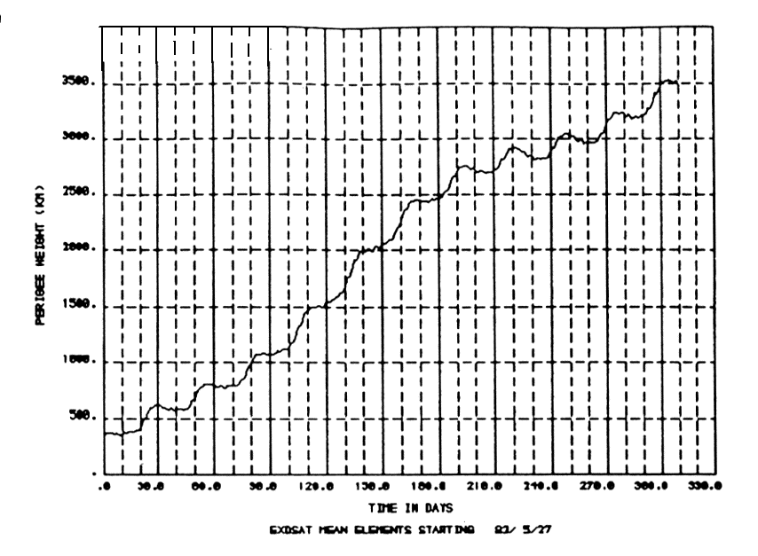
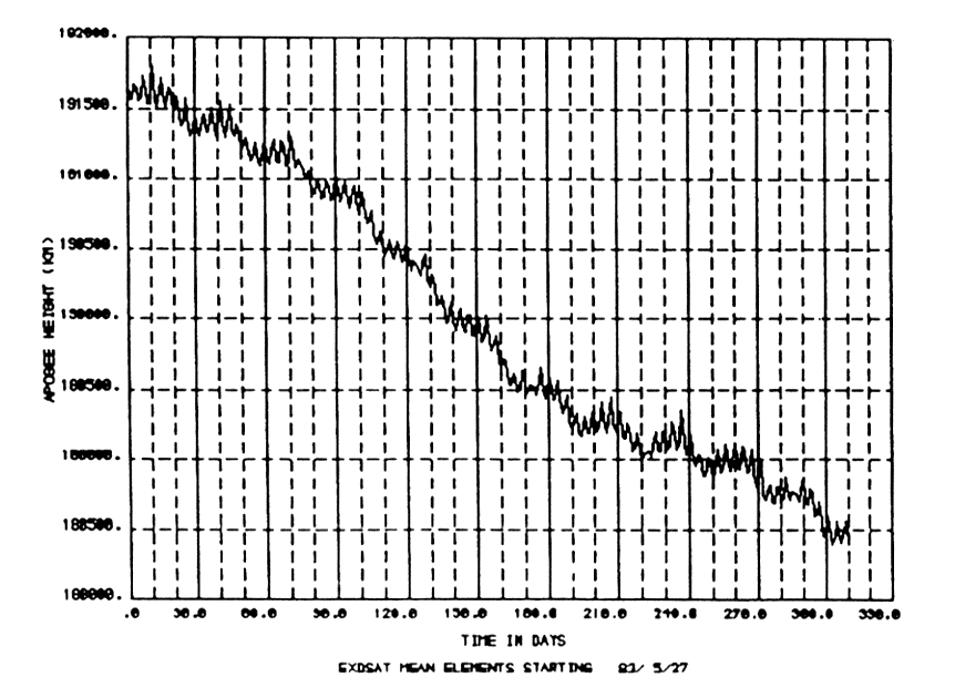
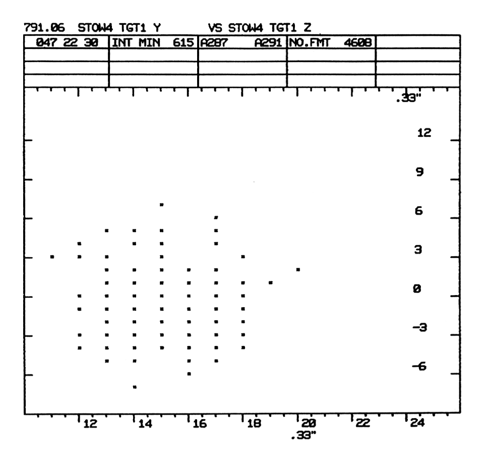
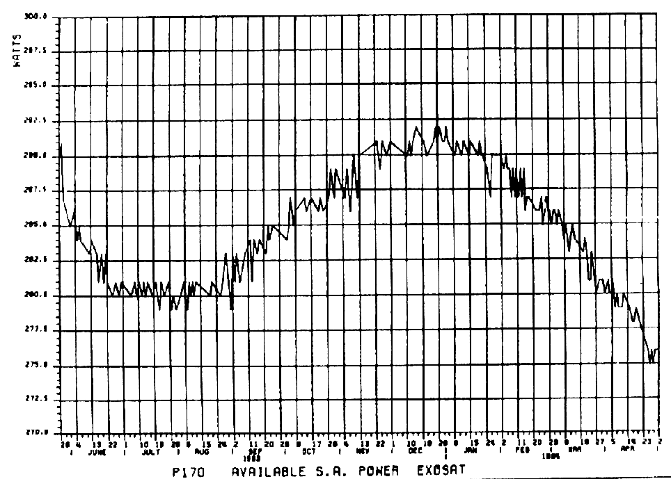
This orbit is perturbed principally by Solar and Lunar gravitation and Earth oblateness and the evolution of the orbital elements since launch has been computed by the ESOC Orbit/Attitude Division. Figures 2 and 3 show the main effect of a steady increase in the height of perigee wi;th a nearly Corresponding decrease in the height of apogee. This trend will, however, soon reverse and the perigee height will reduce such that, without intervention, the satellite would re-enter the Earth's atmosphere some 2.95 years after launch. With the active orbit control system on-board EXOSAT, the possibility exists to use some (or all) of the available hydrazine to increase the perigee height towards the end of life thus extending the orbit lifetime. The total 'delta-V' capability is of the order of 173 metres sec-1 and, used optimally, lifetime extension of slightly more than 1 year is possible. The orbit control system has been recently commissioned and calibrated (17th April 1984) by performing a test manoeuvre of 2 metres sec-1. Satellite visibility from Villafranca is about 86 hours per orbit although in the worst case geometry, loss of signal (LOS) has lasted nearly 16 hours. In general, the LOS periods coincide with the times that the satellite is below 70,000 km altitude (when the payload would in any case be mostly non-operational because of passage through the radiation belts). The orbit determination process is based on ranging measurements from Villafranca which are made throughout the orbit by the SPACON. Ranging is carried out on a non-interference basis with telecommanding with a profile of approximately once per hour close to perigee reducing to once per six hours around apogee. 3.2 The Attitude and Orbit Control Subsystem (AOCS)Attitude control in pointing mode is achieved using gyros for attitude measurement and to control a (nominally) ± 1 arcsecond limit-cycle on each axis by issuing commands to a cold-gas (propane) thruster system. The gyros have a drift correction applied from inertial measurements made by a star-tracker and, in some cases, a fine sun sensor. The limit-cycle control is the so-called "inner-loop" and the updating of the gyros from inertial references is the "outer loop". Slewing from one X-ray source to the next is performed under gyro control with the outer-loop opened. Several problems have been encountered with the AOCS during the first 11 months of operation, the more significant of which are described below. Notwithstanding these problems, we are now approaching manoeuvre/observation no. 1000. Pointing stability of the satellite over extended periods is illustrated in Figure 4, which shows the excursion of the limit-cycle over a typical 10-hour observation period as yielded by the error co-ordinates of the star-tracker. The units on both axes are one-third arcseconds showing that, throughout this period, the pointing direction was maintained within approximately ± 2-3 arcseconds. A 5 arcsecond offset on the abscissa is always superimposed on the limit cycle (see later). On four occasions, spurious "thruster-on" conditions have occurred spontaneously, resulting jn the opposing thruster also coming on to counteract the rotation. This fault has always occurred with the +Y thruster which has a moment arm 16% greater than that of the -Y thruster. With both thrusters on, the 16% imbalance causes the satellite to spin-up until the rate exceeds a threshold (480°/hr) at which Safety Mode circuits cause an autonomous switch to the redundant Reaction Control Equipment (RCE) and place the satellite into a (safe) Y-axis sun-pointing mode. The RCE switch-over clears the "thruster-on" condition. Since this fault has occurred with both RCE's it is thought not to be an intermittent thruster hardware failure. After the third occurrence and some detailed circuit analysis by the spacecraft contractor, it was believed that the fault lay in a component of the prime Attitude and Orbit Control Electronics (A0CE-1) and the decision was taken to switch to the redundant unit, AOCE-2. AOCE-2 was soon discovered to have a fault of a different nature, whereby the gyro drift correction applied to the Y-axis was occasionally erroneously computed. This error caused significant short-term depointing of the satellite (typically one arcminute) and excessive fuel consumption. Analysis of the problem showed that it occurred only when the error co-ordinate from the star-tracer was changing sign on that axis and an operational "fix" was improvised which introduces a 5 arcseconds offset of the Y-axis limit-cycle (see Figure 4). The fourth "thruster-on" event occurred recently during preparation for the orbit control test, with AOCE-2 in operation. It is therefore clear that the fault is not isolated to A0CE-1 and although no explanation has emerged, the problem is under investigation by the spacecraft contractor with highest priority. X- and Z-gyros have shown a progressively increasing drift rate, more or less since launch, which is now of the order of 0.5 °/hr in both cases. The gyros can be "trimmed" by selection of a drift bias equal and opposite to the known drift such that the residual drift-rate seen by the A0CE is close to zero. However, the maximum bias which can be applied is ca. ± 0.3°/hr, which means that the drift compensation computed by the AOCE for the X- and Z- axes is no longer close to zero. Because of the manner in which this is computed (floating-point arithmetic), the accuracy of the compensation decreases as the drift-rate increases. This leads to a progressive degradation in "open-loop", performance on these axes i.e. the attitude offset after manoeuvres and during perigee passage will increase with time. Procedures are being modified to accommodate this behaviour and include an increase in the guide star search areas of the star-tracker. At present the operational impact of this problem is minimal. During several perigee passages in August 1983, spurious triggerings of one of the Safety Mode circuits (circuit B) caused wastage of propane and some impact On the observation programme as a result of the reconfiguration operations. The triggering is believed to be due to an external influence (discharging or radiation) and the Safety Mode circuit has therefore been disabled; no similar problem has been encountered with the Safety Mode A circuit. Other spurious effects have occurred during perigee passage Including jumps In the level of the gyro drift bias on the Z- and S- gyros (skewed). The S-gyro is not "active" in the control loop, however the Z-gyro drift bias jumps lead to a de-pointing of the satellite which has to be rectified Immediately following acquisition of signal (AOS) at Villafranca. 3.3 Power Supply SubsystemThe Solar Array, consisting of 3312 solar cells provides the necessary power to the on-board subsystems and the payload. The 4-panel array is rotated such that it is always pointing towards the sun, whatever the viewing direction of the payload. Figure 5 shows the available Solar Array Power during the first 11 months of the mission; the variation is caused by the eccentricity of the Earth's orbit (perihelion being in January!), superimposed on which is a long-term degradation of the solar cells resulting from ageing and irradiation effects. Power is distributed via a regulated main bus and an unregulated sun bus to various users, and all power lines are protected against shorts in the loads. Excess power is dissipated in a shunt and adjusted regularly to match the demanded power requirements. Two rechargeable nickel-cadmium batteries of 7 Ah each are used to support the eclipse periods, the second of which has just been successfully completed. No problems have been encountered with the performance of the power supply sub-system. 3.4 Radio Frequency SubsystemCommunication with the satellite is via one of two S-band transponders (6W), each connected via an RF switch to one of two conical antennas. Each transponder consists of a transmitter, receiver and power supply and performs all required communications, namely telemetry down-link, telecommand uplink and ranging operations. Although the two antennas provide between them omni-directional coverage, the active transponder has to be commanded via the RF switch to the antenna within coverage of the Villafranca ground station. Measurements of the downlink made at Villafranca show a margin of between 2.8 db and 3.7 db (depending on the propagation conditions) at apogee with the 8 Kbps-1 downlink bit-rate. The performance of the sub-system is well within its specification, which called for 4 kbps-1 nominal and 8 kbps-1 whenever the downlink margin allowed. 3.5 Data Handling Subsystem (DHS)The DHS supports the following functions:
No problems have been encountered with the DHS hardware. The only significant anomaly has been within the 0BC, where intermittent errors in parity bits in the 0BC memory occur for reasons as yet unexplained. This anomaly however has no effect on the operation of the OBC. The software system is the backbone of the science data collection process and has undergone continuous modification and improvement since launch. Several new Application Programs have been developed and the Basic In-flight Software System (BIF) has been re-organised on several occasions to optimise the resources available for the Applications software. A. Parkes Figure 1EXOSAT Computer Support
Figure 2Evolution of perigee height
Figure 3Evolution of apogee height
Figure 4Stability of pointing
Figure 5
LE CCF Update Note No. 1With reference to the status described in the Guide to the LE CCF (EXOSAT Express No. 3 p.36) the following changes have been applied to the LE Current Calibration Files.
Using the terminology introduced in the original article, this CCF is defined as CCF3. The overall SHF key is set to 1983 day 150, and the "last update of cal history" to 1984 day 91. CCF3 has been distributed with the recently despatched calibration history tape and should be used instead of older versions. It is referred to in the latest issue of the FOT handbook.
GSPC Gain CalibrationA precise calibration of the GSPC gains is required because the current procedure of switching off the 28V LE1 power supply line whenever possible to maintain a low average CMAl temperature causes gain variations of the GSPC photomultiplier. Note that use of the in-flight radioactive calibration source (Fe55/Cd109) has been suspended following two occasions of 1malfunction' of the telecommand to move the source from the 'closed' to the 'open' position. In each case, re-transmission of the command was successful, however with no clear explanation of the 'failure' the policy has been to play safe and not exercise the mechanism. The following features may be used to achieve a calibration of detector gain. LED stimulation: This has been performed regularly since day 40 1984 at the beginning and at the end of each observing period (i.e. after the end of the manoeuvre to a source and before the HT switch off at the beginning of the manoeuvre to the next source). The LED line has a width less than that of the detector resolution because the photomultiplier only is stimulated but since practically all gain variations are believed to occur in the photomultiplier tube the data is therefore sufficient to monitor the gain changes. A precise determination of the equivalent energy requires further analysis and observers will be informed of the figure as soon as possible. As of 1.5.84 the gain calibration data in the CCF will be calculated from the LED stimulation at the start of each observation according to the following: The gains gp and gc are defined, as in the FOT Handbook, by: E = N.gp + gc where E = Energy in keV
N = Channel number
gc = -0.035 keV for electronic gain setting =2
-0.105 keV " " " " =1
Therefore, for LED stimulations: gp = ELED - gc
_________
NLED
where ELED = Energy equivalent of the LED (to be determined), and Observers should check the stability of the gain during the observation by comparing the LED stimulation data before and after the observation period. A FOT production problem occurred between day 40 and day 100 and resulted in omission of LED 'observations' from the FOTs. This problem has since been solved and P.I's with prime GSPC observations between these dates will, on request, receive a corrected FOT. Note that an LED stimulation 'observation' is characterized in the observation directory and the telecommand monitor by the In-Flight Test bit being set (or by the telecommand for In-Flight test being on Energy preamp. stimulation) at the same time as the HT's are on. In weak source observations and during slews two Bi lines at energies of 10.75 keV and 13.05 keV are seen. Gaussian distributions may be fitted to these lines to calibrate the detector. The formulae are the same as for LED stimulation with ELED and NLED replaced by the Bi line values. A relatively long exposure time is needed to obtain a reasonable fit (>1h) and the lines are therefore not suitable for checking detector stability (except for long slews before and after an observation), nevertheless as a test of the complete detector they provide a useful supplement to the LED data. The 4.7 keV feature: This feature observed in the GSPC spectra is a function of the detector. It has an equivalent width of ~6O eV, a true width of ~100 eV and is believed to result from X-ray photon interaction with the Xe L shell of the detector gas. For strong sources and where no other method is available it may be used to determine the gain, and in any case it provides a good consistency check on the other methods. Note that source spectral features may distort the detector feature. Observers should as far as possible utilise all three methods described here to give consistent results and hence confidence in the gain calibration. T. J.-L. Courvoisier
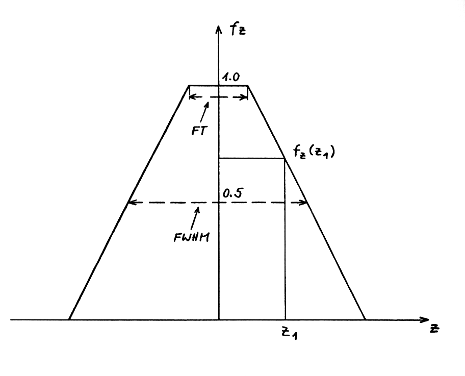
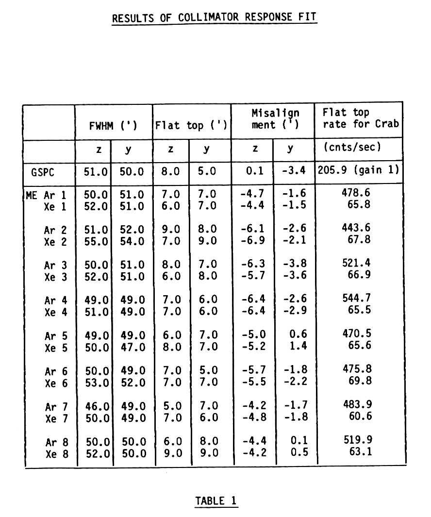
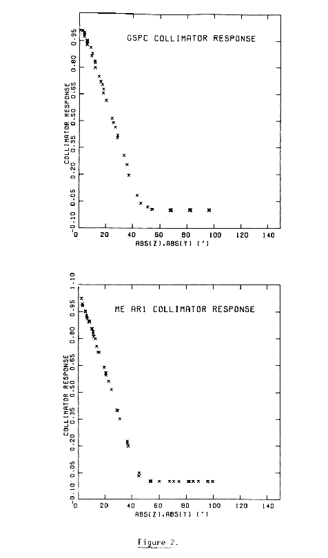
ME and GSPC Collimator Response ProfilesA Crab Raster scan (69 Observations with a typical exposure time of 10-20 minutes) was carried out on days 276/277 to determine the in-orbit ME and GSPC collimator response profiles. Most of the pointings placed the source in the 3rd (in spacecraft co-ordinates z<0, y<0) and 4th (z>0 and y<0) quadrants, concentrated around the expected origin of the collimator response at z = y = 0. Collimator elements are identical in design for all ME detectors and the GSPC and pre-launch calibration measurements demonstrated that the response profile is best represented by a rectangular-base pyramid defined by 4 parameters. These are the flat top (FT) and the FWHM in z- and y- directions (fig. 1). In the special case of a square base zFT = yFT, and zFWHM = yFWHM. For a given point (z,y) and a collimator origin at z = y = 0 the response fC = fC (z,y) can be defined as: fC (z,y) = fZ * fY with
Since each detector is not perfectly aligned with respect to the spacecraft system (star tracker x-axis does not equal detector 'optical' axis) |z| and |y| must be substituted by |z - zM| and |y - yM| where zM, yM define the misalignment of the detector. The unknown parameter of the collimator response together with the flat top count rate can be derived by a simple minimum x2 analysis of the raster scan data. All results are corrected for systematic effects caused by misalignment in the 'co-aligned' position between the ME array halves and undersampling of the data for the strong CRAB source.
system. M. Gottwald Figure 1:Collimator response model
Table 1:Results of collimator response fit.
Figure 2:Typical ME Ar detector and GSPC collimator responses.
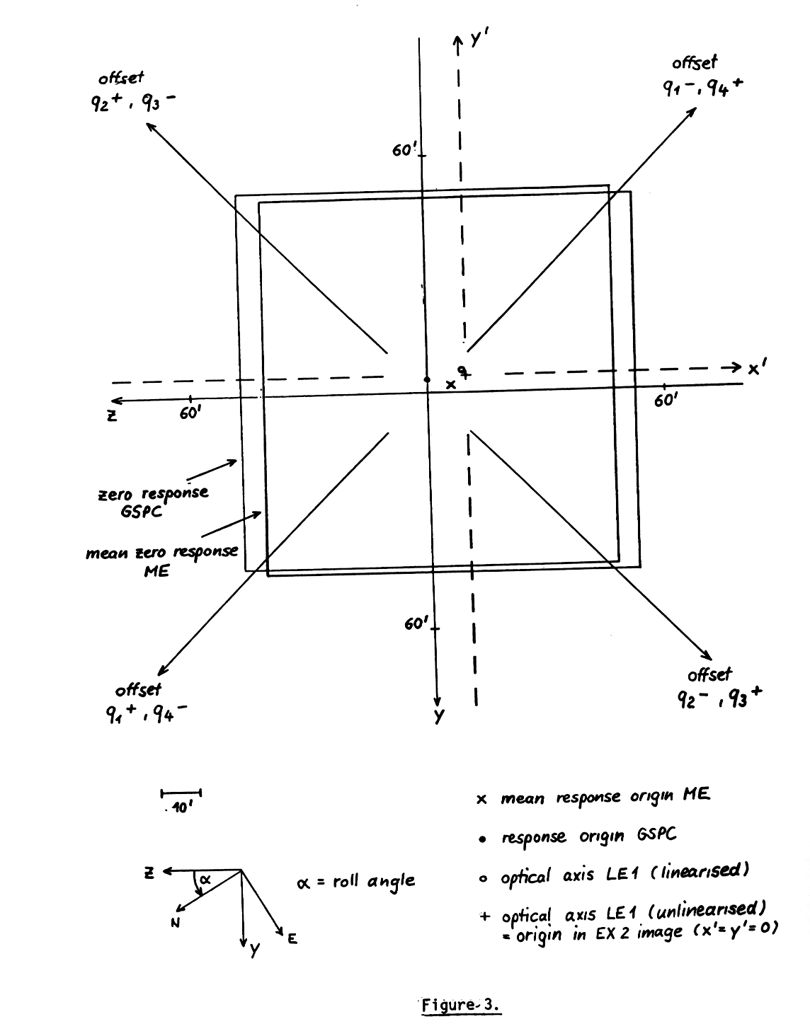
Figure 3:Misalignment ME/GSPC/LE1 with respect to spacecraft reference
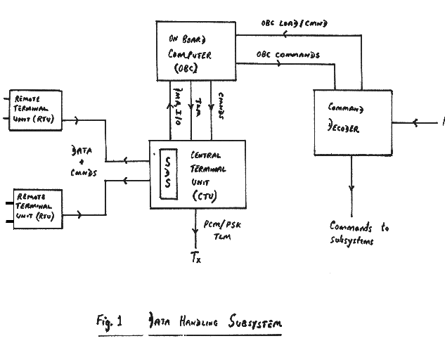
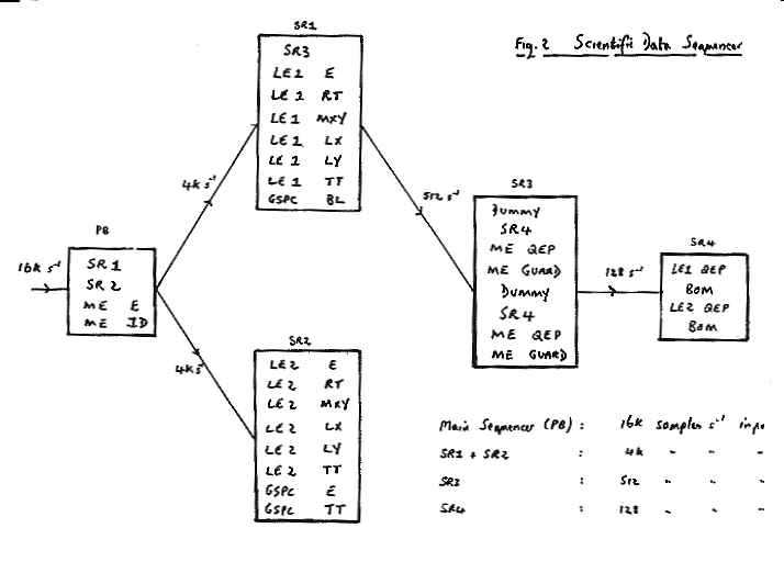
EXOSAT Timing and Payload 'dead' times1. GeneralA prime objective of the EXOSAT mission is to time each X-ray event to an absolute accuracy of 100 µs and a relative accuracy of 10 µs for any 24 hour period, and to monitor regular and irregular intensity variations of X-ray sources with timescales from 10 µs to 80 hours. Accurate on-board timing and subsequent conversion to universal time via reference timing at the ground station is therefore required. Reference is made to Section 4 of the FOT Handbook for information on Universal time conversion. Corrections for experiment 'dead' times, data handling subsystem/ OBC sampling effects and 'off' times in certain OBC modes must be made for all intensity calculations. The purpose of this article is to summarise the timing and 'dead time' characteristics of the payload, 0BC and data handling subsystem. 2. Basic ConsiderationsData is transferred from the experiment output channels via remote terminal units to the 0BC, under control of the central terminal unit and scientific data sequencer Fig. (1) and (2) using Direct Memory Access (DMA) in toggle mode with 512 8 bit data words acquired per Direct Memory Access (DMA) cycle. The basic clock frequency is 217 Hz, i.e.
Sample pulses are issued to the relevant experiment output channels according to the set-up of the scientific data sequencer (Figure 2) which allows sample rates of 16k, 8k, 4k, 2k, 1k, 512, 256, 128, 64 and 32 s-1 to be commanded on any channel (in the example shown, 4k samples per sec on the ME energy and ID word channels, 512 s-1 all LE1, LE2 and GSPC event data, 256 s-1 ME guard and QEP, 64 s-1 BOM and 32 s-1 LE1 + LE2 QEP). Thus in 1 SWC (software cycle: 31.25 ms) for this example a buffer of 512 words as shown in acquired in the 0BC:
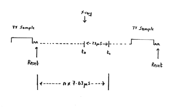
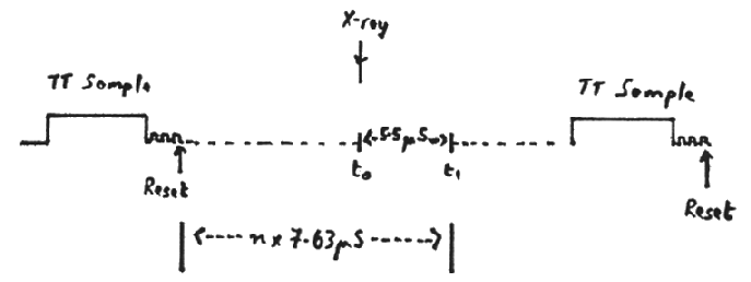
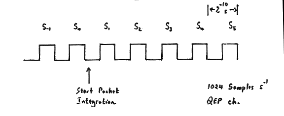
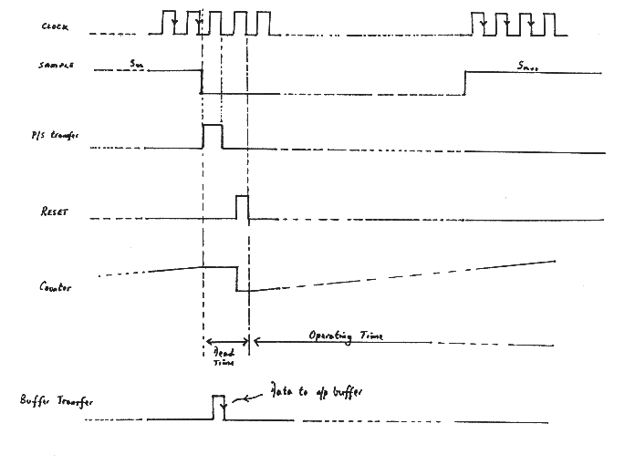
xrefer to Section 6 Each data word corresponds to a unique 61.04 µs sample pulse within the SWC; this forms the basis of correlation to universal time. Consider the sampling of one experiment output channel (Figure. 3) eg. LE1 QEP according to the above SDS set-up, with a sample pulse repetition of 31.25 ms (32 samples s-1) All experiment output is double buffered electronically, that is data is clocked into a buffer register as the data becomes available, it is transferred to the output register on the next sample pulse and from the output register to the OBC on the subsequent sample pulse. Details of this transfer are shown in Figure 3. Note:
The above refers specifically to all counters, eg. ME/LE/QEP, ME guard and for most reasonable sample rates the dead time is negligible. For event data channels (energy, position, etc...), two clock pulses are in principle required for the transfer to the output register and reset of the buffer register per channel, but because of the need to ensure that event data is unambiguously referred to a complete set of samples, transfer takes place on the channel sample pulse but the reset is effected for all channels simultaneously on the clock pulses after the last channel sampled in the sequence. (NB: Depending upon which channels are sampled in any particular SDS set-up, the reset can be telecommanded accordingly). Again the total dead time because of sampling is two clock pulses per sample interval, however, other considerations are more important (refer to section 3). If no reset were commanded, each channel would behave independently, in a similar manner to the QEP counter. Note that for the ME experiment an additional clock pulse is required for completion of the transfer to output register and buffer, ie:
3. Internal Experiment Timinga. LE ExperimentsPSD
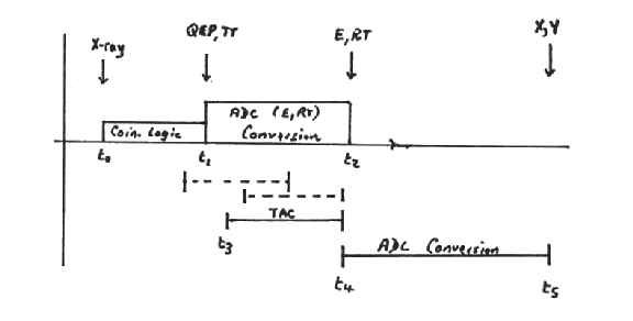
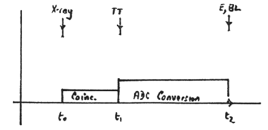
Incident X-ray at time t(0) (referred to conversion in detector). Coincidence logic takes t(1) - t(0) approx. 22 µs to check >Emin, < Emax and Guard.
ADC conversion begins at t(1) and takes t(2) - t(1) = 33µs At t(2): ADC data (E, RT) available in corresponding buffer registers. t(3): Start of time-to-amplitude conversion of time difference between zero-crossings of X+X- preamp signals and Y+Y- preamp signals. Maximum zero crossing time: ~45µs from t(0). t(4): Completion of TAC 25-45µs from t(0)
At t(5): Position data (MSB's, LSB's + signs) available in buffer registers. NB :
CMA Note that, for CMA measurements, the qualified events counter is in fact a counter of the valid position pulse, derived from each preamplifier signal exceeding the position coding threshold and zero crossing times within range. 'QEP' and time tag are formed only at time t(3) in the diagram which is 25-45 µs after the event arrival. Thus the time tag data refers to the time from the reset to t(3). Note that the QEP is always 1 per event because it denotes a valid position and a reset must therefore be given before a second event can be processed. b. ME Experiment
Incident X-ray at time t(0) Coincidence logic (SCA LL/UL + vetos) takes t(1) - t(0) ~ 5.5 µs
ADC conversion begins at t2 (t(2)-t(0) ~ 7 µs) and takes 33µs (t(3) -t(0) = 40 µs). At t3: Energy data available in buffer register. NB:
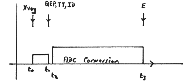
c. GSPC Experiment
Incident X-ray at time t(0) Coincidence logic (SCA LL/UL, RT veto) takes t(1)-t(0): Time tag counter stopped at t(1) and available in output buffer QEP (HK channel) incremented ADC conversion begins at t(1) and takes 33µs: t(2)-t(0): Energy/burst length data in output buffer at t(2) NB :
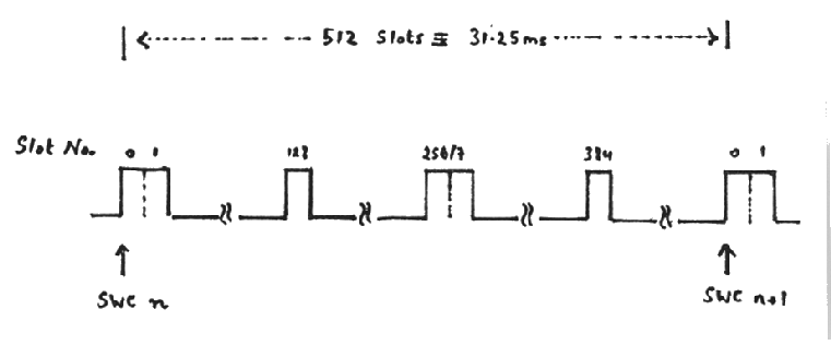
4. OBC Data TimingIn 1 SWC of 31.25 ms, 512 words are transferred via a DMA channel into the OBC input buffer, the content of each word corresponding to the sample sequence established in the SDS (eg. Figure 2). Certain fixed sequencer slots in the 31.25 ms cycle must be used for non-experiment data transfers on the CTU bus, viz:
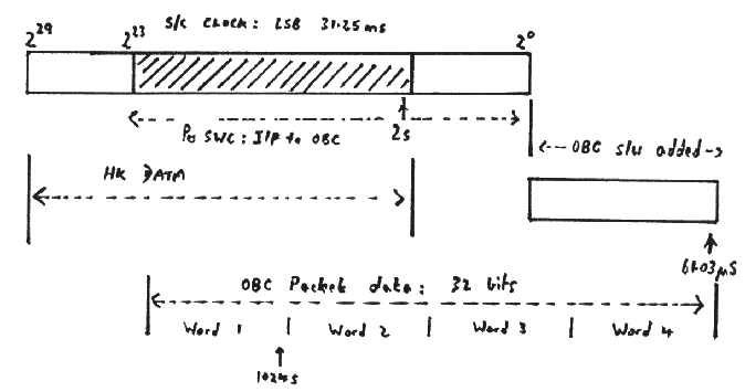
Thus words, 0,1,128,256(257)and 384 in the OBC input buffer do not contain experiment data (irrespective of the RTU channel in that slot in the SDS). Each SWC, 24 LSB's from the 30 bit spacecraft clock are read into words 0,1,128 and give the relative on-board time at which the first sample pulse in the sequence is issued, to an accuracy of 31.25 ms as shown:
9 bits are added to the 24 bit spacecraft time to give a resolution of 61.04 µs and the 32 LSB's (1 MSB omitted) are transmitted to ground as part of the OBC packet header data. The LSB (61.04 µs) gives the relative timing of a specific sample pulse within the 512 word cycle (depending on the OBC mode) eg:
(NB: Fine timing, ± 7.63 µs is provided by the experiment time tag). The 0BC packet time can be related to the overall space-craft clock time on ground (2s LSB) transmitted once per format via the common bits shown shaded in the diagram. Absolute time correlation is provided by tagging the arrival of each format pulse at the ground station, correcting for propagation and other delays and equating this with the on-board spacecraft clock time for that particular format. 5. Algorithms for Time Calculationa. Direct Mode with Time TagConsider the regular sampling of the time tag channel of any experiment (NB if the time tag channel is sampled, it must be the last channel sampled with reset commanded on the time tag sample):
In the direct mode, there will normally be periods during which the 0BC does not process the incoming buffers, in order to match telemetry allocation to data rate; events arriving in these times are lost and the periods constitute 'dead time' of the system. Suppose a new direct packet collection starts at (A) and successive samples of the time tag channel are S1-S6 etc. Event data read into the OBC with sample S1 must correspond to an X-ray detection during the period S1 to S0 with a time tag relating to S-1 (NB: at S0 the event data is clocked from the buffer registers to the output registers). Similarly for any event data with sample Sn the time tag counter refers to a time t after sample Sn-2. The OBC counts zero data samples; this counter is reset at the beginning of a packet accumulation period and whenever an event is acquired. Thus a second event X2 has a time tag associated with S4 and is read into the OBC input buffer with S6; it therefore has an associated zero sample counter (relative to X1 with S1) z2 = 4 (samples S2 - S5).
R then refers to the leading edge of the sample pulse WF therefore 1st time tag sample is at: R + (WL-WF) x 2-14
Let T(1) = relative on-board time of event with time tag t(1) T1 = R + (WL - WF + 1) x 2-14 + kx2-17 + (z1 - 2) x 2-9 + t(1) = R + (WL - WF + 1) x 2-14 + (z1 - 2) x 29 + (t(1) + k) x 2-17 assuming 512 s-1 sample rate In general: Tn = Tn-1 + (zn+1) x 2-9 + (tn - tn-1) NB:tn should be corrected for the additional clock pulse counts while the coincidence logic accepts a valid event, i.e.
b. Intensity Modes/HistogramsWith no time tag data, the relative on-board time can be determined to 2-14 secs, with an accuracy according to the sample rate.
Reference time (R) refers to start of packet integration. Therefore S1 leading edge occurs at R + TQ x 2-14 where TQ = offset to first QEP sample. Therefore reset of 1st QEP sample is at: R + (TQ+1) x 2-14 + 2 x 10-17. However, the QEP sample at S1 refers to the integration period S-1 to S0. T1 = R + (TQ - 1) x 2-14 + 2 x 10-17 Tn = Tn-1 + 2-10 These figures give the start of the integration period for the QEP counts with an accuracy of 2-14 s. 6. 'Special Effects'a. 'Operational Constraints'The main constraints on programming the SDS are to cater for the non-experiment slots (Section 4). At these times no sample pulse is issued to ari experiment channel, irrespective of.whether a valid RTU channel address is programmed in this slot. It is fairly easy to account for slots 0, 128, 256, 384 by programming a dummy address as shown in Figure 2, subroutine 3, slot 1. However, slots 1 and 257 are more difficult; in the. example shown no sample pulse would be issued to the LE2 energy channel corresponding to slots 1 and 257, hence no transfer from output register ; to OBC or from buffer register to output register, and missing energy data. If an event were present in the output register (buffer registers are set to zero on the general reset). On the next sample set the missing energy word would be transferred to the OBC (output registers not reset) together with zero data if no further event were present in the buffer register. Workspace parameters are defined to account for the above as required, and the reference time is uniquely referred to the sample of data which is OBC processed:
OR
In intensity modes with counters (QEP/guard) sampled in slots 1 and 257, the OBC inserts a zero in each data packet to account for the missing sample slot 1 (0 is read into the OBC in any case for slot 257). Word 2 in the data packet (= 1st sample) then refers to the normal integration period but word 3 (= 2nd sample) refers to double the integration period, covering the missing slot. This complication should be avoided if possible by SDS programming. b. VHR ModeA special mode in which the OBC operates under real time clock control and issues sample pulses for a limited fraction of time to accumulate sufficient data to match the total core and TM available. The telemetry bit rate must be 4kbs, (otherwise one 8 bit word only would be transferred to the OBC at slot 257). Two sample rates are currently defined, vis 8k s-1 and 1k s-1 . For 8k samples s-1, the SDS is as follows:
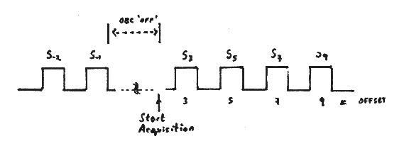
Timing information refers to the first valid sample of the ME parallel channel i.e. slot 3 of the main sequencer (MS). In this mode, no sample pulses are issued for a certain period and then data is collected for a number of SWC's (approx. 3 for 8k s-1 and 7/8 1k s-1) depending upon core allocation. Thus, the sampling of the ME parallel channel is as shown:
In the middle of the data (slot 1 of each SWC) missing sample pulses will give one fewer set of samples and the slot 3 sample is thus integrated over 2 x sample period. c. OBC 'Off' PeriodsAll modes for which output data exceeds telemetry allocation.
D. Andrews Figure Captions:
Page authors: Lorella Angelini Jesse Allen HEASARC Home | Observatories | Archive | Calibration | Software | Tools | Students/Teachers/Public Last modified: Thursday, 26-Jun-2003 13:48:32 EDT HEASARC Staff Scientist Position - Applications are now being accepted for a Staff Scientist with significant experience and interest in the technical aspects of astrophysics research, to work in the High Energy Astrophysics Science Archive Research Center (HEASARC) at NASA Goddard Space Flight Center (GSFC) in Greenbelt, MD. Refer to the AAS Job register for full details. |


