BurstCube: Instrumentation
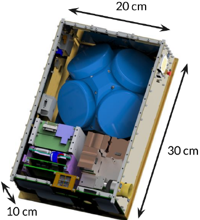
Angled view of the BurstCube satellite schematic (minus solar panels) showing
the total dimensions (6U where 1U is a CubeSat unit of volume equal to 10 x 10 x 10
cm2) with the 4U sized instrument shown in blue.

Front and back sides of BurstCube satellite, showing solar panels, communications
equipment, and the location of the instrumentation.

Cross section of the detector (one of four). CsI appears in orange, SiPMs are grey.

Diagram showing three of the four detectors mounted together. The outer housing,
shown here in grey, is made of thin aluminium which is transparent to gamma rays.
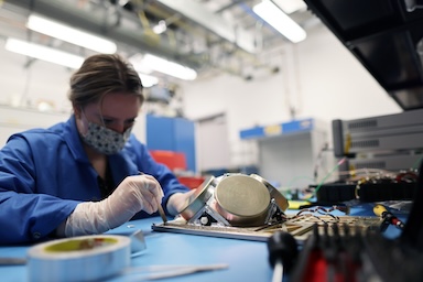
Engineer Julie Cox applying aluminized tape over joints, screws, and gaps in the instrument suite.
Stray light will create false triggers. After applying the seals, the instrument is tested by shining a
laser over all the surfaces to verify the sealing. The large golden colored disks are the four
single quarter detectors (SQDs) in their flight-ready aluminium cases. Photo credit: NASA/Sophia Roberts.
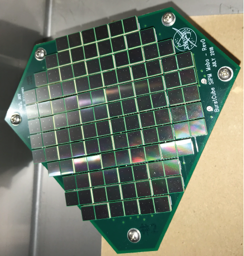
The silicone photomultiplier (SiPM) array with 116 detectors mounted on the front end
electronics (FEE). Each individual SiPM element is 6 mm a side.
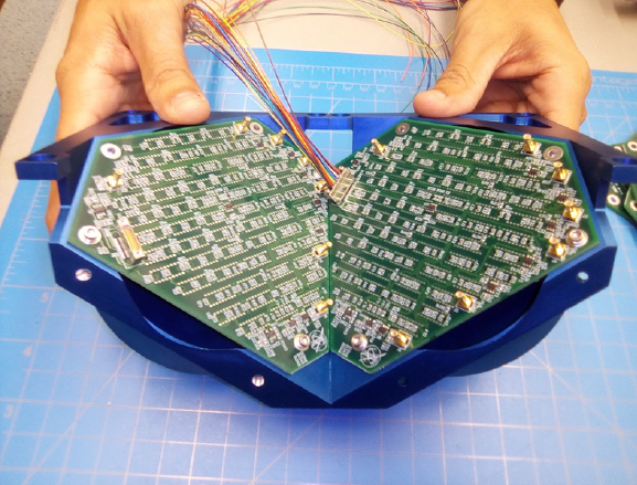
Two FEE boards in the aluminium housings to check for fit.
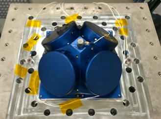
Detector (one flight test, plus three “dummy” placeholders with identical mass to
the final instruments) mounted on the vibration table to emulate launch stress.
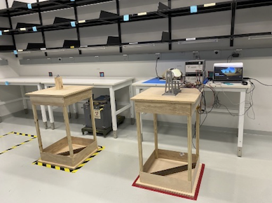
The flight-ready SQDs (held in a metal frame on the table outlined with red tape) during
calibration of the instrument response to match the channel-energy relationship,
energy and angular dependent detector response, effective area, and energy range and
resolution.
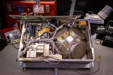
The assembled BurstCube satellite, with lid top open to show the interior arrangement including the
SQDs and flight electronics. Photo credit: NASA/Jeanette Kazmierczak.