

Next: Low Pulse Height Tails
Up: Position-Sensitive Proportional Counter (PSPC)
Previous: 3.1 PSPC Overview
Primarily [Snowden1988]

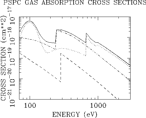
Figure 3.2:
The absorption cross-sections of the various components which
comprise the ROSAT PSPC counter gas. The curves are as follows
at the far right from the top of the plot: the total cross
section, the cross section from xenon, the cross section from argon,
and the cross section from methane.
It can be seen that for E>245 eV (the Ar L-edge) one gas alone
(Ar for  , Xe for E>672 eV)
dominates the absorption. For E<245 eV the component
dominating the absorption switches smoothly between Ar and Xe
(from Snowden Memo TN-ROS-ME-ED52/31 [Snowden1988]).

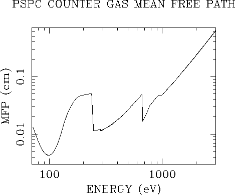
Figure 3.3: The mean free path of the ROSAT PSPC assuming
a mixture of 65% argon, 20% xenon and 15% methane.
Photons of energy  eV (and just above the
absorption edges) are absorbed at a depth
less than the characteristic size of the resulting secondary
electron cloud.
At these energies a fraction of the secondary electrons
are therefore lost to the window, and thus giving rise to a
low pulse height tail to the PSPC pulse height distribution
response to a monoenergetic X-ray input
(see Sect. 3.2.1).
The drift region, i.e., separation between the window and the
K1 cathode, is
  mm
(see Fig. 3.1 and
[Snowden1988]).
The anode and cathode grids are contained in a gas-filled counter housing
containing a mixture of 65% argon, 20% xenon and 15% methane.
An X-ray photon, passing through the thin plastic entrance window,
will be photo-electrically absorbed by the counter gas producing
a photo-electron.
The relative contribution of each of the gas components to the absorption
cross-section is shown in
Fig. 3.2,
and the resultant mean free path (i.e., absorption depth) in
Fig. 3.3.
The primary electron is thermalized and in the process causes the
ionization of other gas atoms forming a secondary electron cloud.
The positive ions (including the ion initially ionized) can also add to
this cloud by Auger and shake-off processes when energetically allowed.
The mean energy required to create a secondary electron is approximately
constant over the entire energy range of the PSPC (deviations are most
likely to occur just above the gas absorption edges).
The probability distribution function for the number of secondary
electrons can be described by a Gaussian whose width is given by
the modified Fano factor, f', which takes on integer values only
(and is obviously truncated at zero).
The number of electrons contained within the secondary electron cloud
is therefore approximately proportional to the energy of the
incident photon (giving rise to the name of the device).
The secondary-electron cloud drifts through the K1 cathode grid
toward the A1 anode grid
(Fig. 3.1).
When the electrons of the charge cloud approach closely enough to an anode,
the electric field strength becomes sufficiently high for the secondary
electrons to ionize additional gas atoms (i.e., the energy that the
electron gains from the electric field between collisions is greater than
the ionization energy of the gas) causing the charge cloud to be amplified
by a (gain) factor of  .
The avalanche of charge onto the anode leads to a charge pulse
at the anode and an induced signal at the cathodes,
which are all processed by charge-sensitive preamplifiers.
The cathode grids are divided into 25 (K1) and 23 (K2) cathode strips.
Each strip consists of seven or eight cathode wires tied together,
and is connected to an independent preamplifier.
Depending on the energy of the photon,
a cathode signal is typically induced on 3 to 5 strips (although,
ghost images can occur for events with pulse heights
corresponding to energies  keV, -
see Sect. 3.5.4).
These signals are digitized by means of pulse shapers, peak detectors,
and analog-to-digital converters (ADC).
After checking for validity of the event, the
position is calculated by adopting a centre-of-gravity calculation.
To get the position in both co-ordinates, the two cathode grids are
arranged perpendicularly to each other
(Fig. 3.1).
The wires of the anode grid are connected in parallel to
one preamplifier with pulse shaper, peak detector, and ADC.
Its signal is used to obtain the energy of the X-ray photon
and also as the trigger signal for the cathode read-out electronics.
The time required by the electronics for conversion, validity checking,
and position calculation is <1 ms, leading to a maximum average
event rate of  .
.
In conjunction with the signals of the ``veto'' anode (A2),
the signals of the outer cathode strips of K1 and K2 are combined
in an anti-coincidence circuit.
The gas depth of these veto counters is such that ionizing particles
as well as resonant scattered X-rays (coming from the frames and
counter body) are detected
(see Sect. 3.6.1).
The achieved background rejection efficiency is around 99.8%.


Next: Low Pulse Height Tails
Up: Position-Sensitive Proportional Counter (PSPC)
Previous: 3.1 PSPC Overview
If you have problems/suggestions please send mail to
rosat_svc@mpe-garching.mpg.de

