What Are Undershoots And Optical Loading?Return to: Analysis Threads | Analysis Main Page
OverviewThis thread introduces the concept of optical loading and undershoots. We discuss what undershoots are, and how they arise. In short, optical loading is the presence of optical photons that enter the NICER detectors. Optical loading tends to increase the rate of detector resets which are called undershoots by the NICER team. Read this thread if you want to: Understand more about undershoots and optical loading Last update: 2023-09-08 IntroductionNICER detectors are known as Silicon Drift Detectors, or SDDs. SDDs are fast-response silicon detectors that enable NICER's high throughput and fast temporal response, while maintaining CCD-like spectral resolution. Due to how SDDs work, they periodically need to be reset, and that reset is recorded in NICER's event list as an "undershoot" event. Typically, although not always, undershoots are dominated by the amount of optical loading experienced by the detectors. A brief summary of this thread is
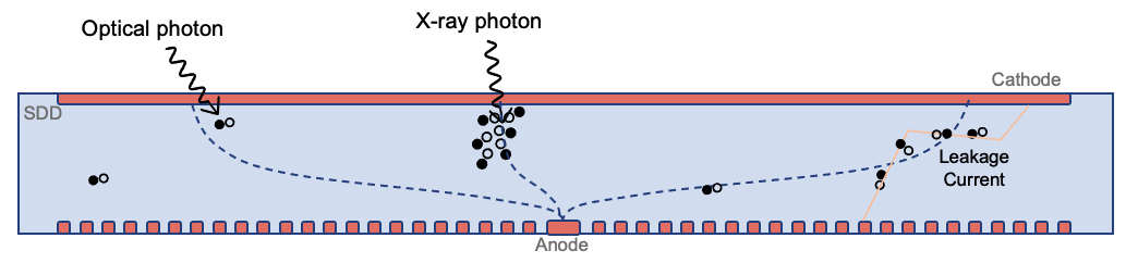
Please note that undershoots are quite different from overshoots. Overshoots are discussed on the What Are Overshoots? analysis thread page. How SDD Detectors WorkNICER's Silicon Drift Detectors (SDDs) are circular silicon-technology devices that are sensitive to X-ray photons. X-ray photons enter the silicon device and convert to electrons where they drift to the read-out anode and are recorded. Figure 1 shows a highly simplified diagram of an SDD.
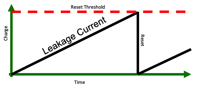
In addition to being sensitive to X-ray photons, SDDs are also sensitive to other processes that may inject charge into the silicon. Charge is typically injected by an excitation, which creates an electron-hole pair. Electrons drift to the anode electrode where they are accumulated and amplified. The processes that inject charge include X-ray photons, optical photons (which typically create one electron-hole pair per photon), and charged particles such as cosmic rays (not shown). Also, electron-hole pairs may be created in bulk silicon by thermal excitations. It is for this reason that NICER detectors are kept at low temperatures, typically -55 Celsius. Leakage current processes may be enhanced by defects in the silicon crystal, which may either be inherent in the manufacturing process, or created by particle radiation processes. All of these electrons are swept to the anode and are read out. Even in perfectly dark conditions, with no optical light and no X-ray photons, a small amount of leakage current is present, which is typically constant on the time scale of months. The anode may be thought of as a capacitor that receives the electrons and charges gradually due to the processes mentioned above. At some point, the charge (and therefore voltage) on the capacitor reaches a maximum limit and is reset to zero. This is known as a detector reset. This process is illustrated in Figure 2.
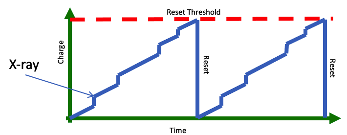
The reduction of anode charge from a large value to zero causes the read-out electronics to typically measure a large negative pulse, which is recorded as an undershoot reset event. Here "undershoot" means that the event was negative, and thus not an X-ray. The reset itself takes a few hundred nanoseconds to complete. Please note that detector resets of this type are completely normal and represent a well-functioning detector. Before and after a reset, NICER's SDDs are sensitive to X-rays. As shown in Figure 1, there are many sources of charge that may be amplified by the detector. Although the anode charges gradually due to the steady leakage current and injection of optical photons, X-rays and charged particles inject a step function of charge. The addition of small steps is illustrated in Figure 3. Typically these steps are much smaller than the full-well capacity of the anode. It is these steps that represent the amount of energy injected, and thus pulse height read out by the electronics is used for spectral analysis.
The time interval between resets is determined by the charging rate of the anode. However, the time interval between resets, or equivalently the rate of resets, is an important diagnostic measure of how the detectors are performing. We will discuss this more below. Where Are Undershoot Resets Recorded?Undershoot reset events are stored in the event list just as normal X-rays are stored. They are located in the raw per-MPU event files, also known as the "uf" (unfiltered) event lists, in the xti/event_uf/ subdirectory of each observation. Each event has an undershoot flag bit set in the FLAGS column of the event list. Undershoots are an interesting enough diagnostic that their count rate is also stored in the per-observation filter file. See Managing NICER Filter Files for more information about NICER filter files. A key quantity in the filter file is FPM_UNDERONLY_COUNT, which is the average per-detector undershoot rate. As a reminder, this average rate is an indicator of the average detector performance. Why Do We Care About Undershoots?Variations in undershoots represent a change in the performance of the detectors. Very high undershoots can lead to degraded spectral resolution and a slightly altered low energy threshold. As undershoots increase, the number of non-X-ray electrons injected increases also. This causes the energy scale to shift. This shift must be accounted for by the gain calibration model. As undershoots increase, the resolution becomes less sharp. This change in resolution must be modeled by the response calibration model. As of HEASoft 6.29 and Calibration release xti20210707 (released July 2021), these models are improved to deal with higher levels of undershoots. Changes in undershoots are also correlated with noise peak events which appear at the lowest energies, usually below 0.35 keV. As undershoots increase, the noise peak count rate increases, the centroid energy increases, and the noise peak becomes broader. Thus, from a perspective of reducing noise, lower undershoots are desireable, and may impact the usable energy range of NICER. What Are The Sources of UnderShoots?As discussed above there are several souces of undershoots.
From our point of view, however, the largest contributor to large undershoots is optical loading. Let us discuss optical loading further. What is Optical Loading and Where Does it Come From?Optical loading is a technical term for optical photons entering the active detector volume. Typically one optical photon will convert to one electron-hole pair. This may seem like a small number of electrons compared to, say, an X-ray which injects ~hundreds of electrons per X-ray photon. In addition, the detector housing has an optical blocking filter that reduces the transmission of optical light by several orders of magnitude. However, in cases where optical photons are plentiful, the overall optical loading rate may still be high. Where do the optical photons come from? The strongest source of optical loading is the sun. When NICER points near to the sun, typically within 60 degrees of the sun, undershoots begin to increase significantly. This represents optical light that is scattered off of NICER surfaces and into the detectors. Undershoots may become especially high for pointing angles between 45-60 degrees from the sun. Other sources of optical light are the International Space Station structure, including solar panels, and bright earth. Light may also enter through pinholes in NICER's exterior blanketing. Optical light from the science target is typically not a strong source of optical loading. Thus, optical loading will be strongest when NICER points near to the sun, and during orbit day. During orbit night and pointing angles farthest from the sun, optical loading will typically be minimal. What Comes Next?Please see the NICER Undershoot Filtering Recommendations analysis thread for more discussion on screening strategies for undershoots. Modifications
|


- HEASARC Director: Vacant
- NASA Official: Ryan Smallcomb
- Web Curator: J.D. Myers
- Last Modified: 8-Sep-2023